

CYPEHVAC Ductwork is a tool to carry out the analysis and design of duct network projects, based on an architectural model located on the BIMserver.center platform.
"CYPEHVAC Ductwork" is integrated into the Open BIM workflow via the BIMserver.center platform.
Description
"CYPEHVAC Ductwork" is a tool that has been specially designed to carry out duct network projects, enabling their analysis and calculation.
Calculation methodology and standards
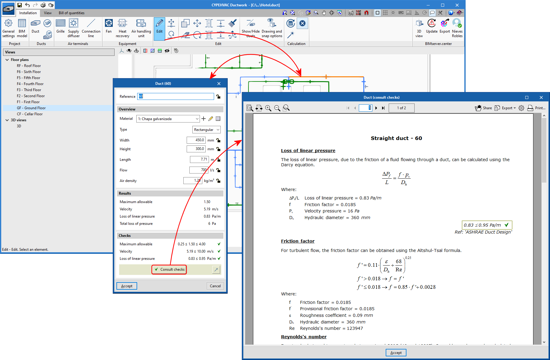
The calculation methodology used for each element is detailed by clicking on "Consult checks", located in the properties panel of each element.
The calculation methods have been carried out in accordance with ASHRAE standards.
Getting started
The software is designed to carry out the design of duct networks with grilles and ventilation equipment. It allows the installation elements to be introduced by importing the information of the architectural model of the BIM project, or simply with DXF-DWG and DWF templates or images (.jpeg, .jpg, .bmp, .wmf).
To start working with the program the user must connect the job that they are starting to a BIM project on the BIMserver.center platform, or generate a new project.
If users connect to an existing project that includes a model with the building geometry (generated by CAD/BIM programs such as IFC Builder, Allplan, ArchiCad or Revit), "CYPEHVAC Ductwork" can import the floor organisation of the building. If the architectural model is generated by IFC Builder, the DXF or DWG templates that contain that model can also be imported, or the model which IFC Builder generates (from the introduced construction elements) when exporting the model to the BIM project.
Work environment. Introduction of the installation elements
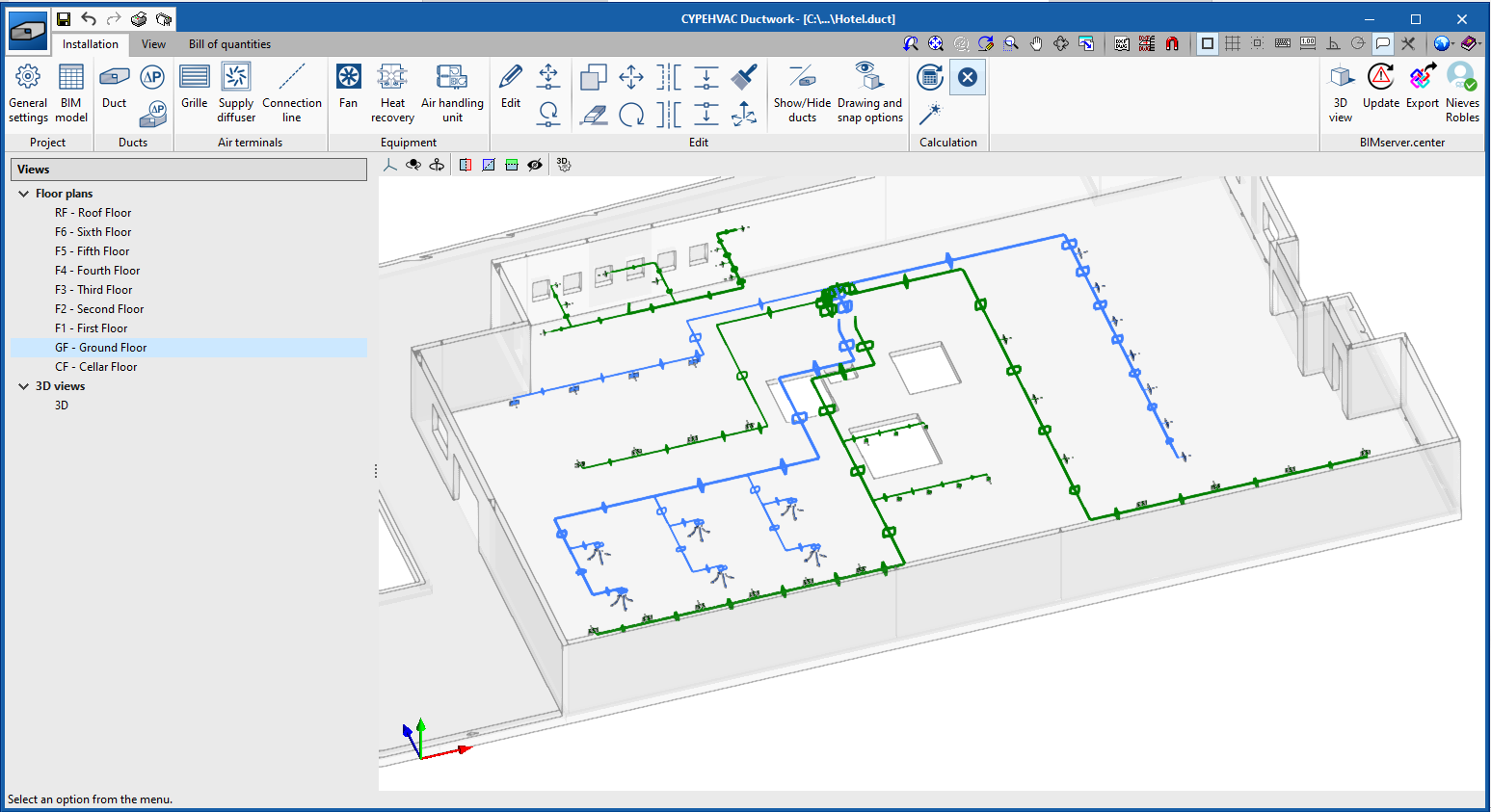
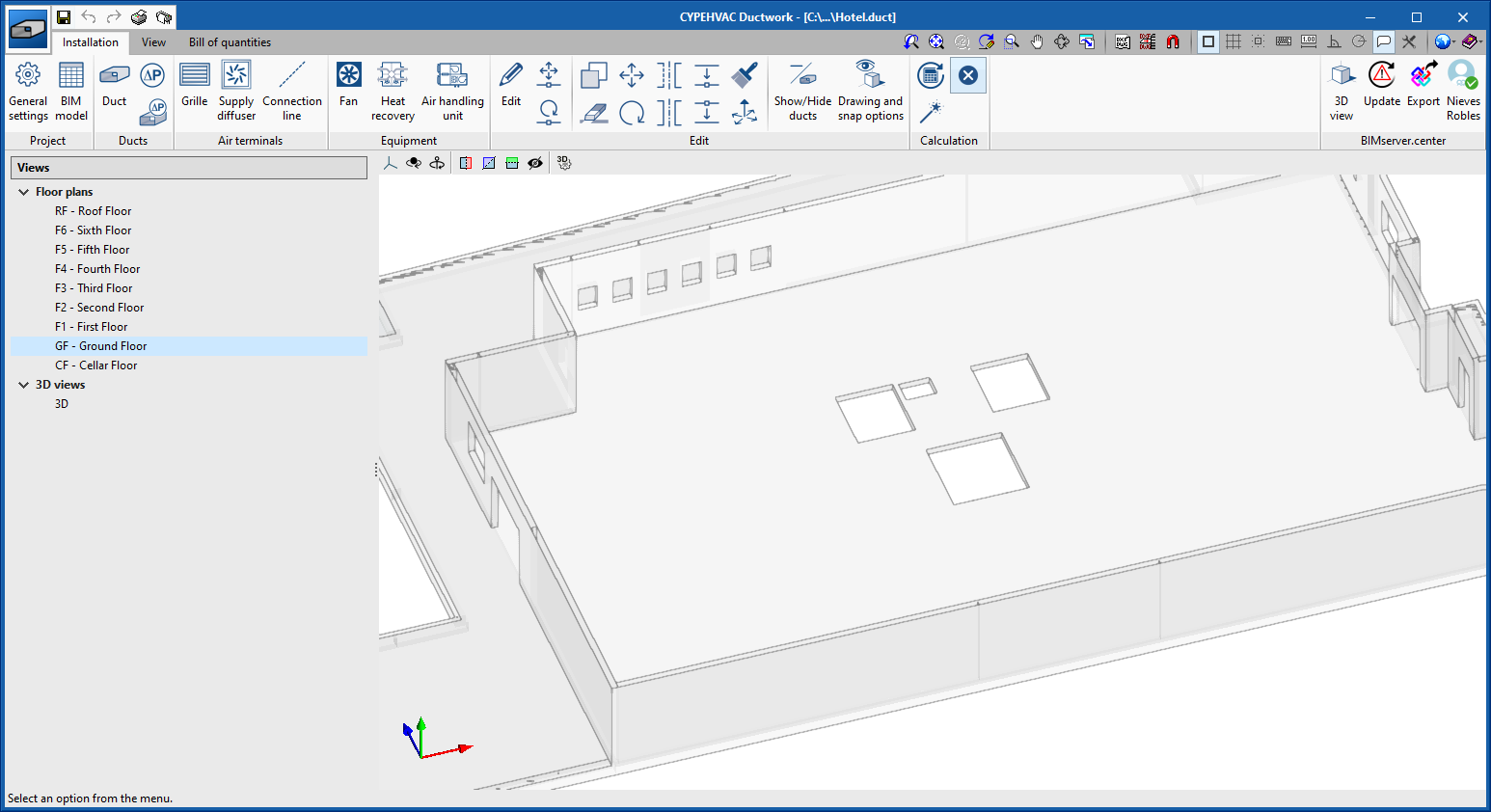
CYPEHVAC Ductwork presents a 3D work environment that allows duct installations to be designed quickly and easily, both in a 3D view as well as in any other type of 2D view (floor plan, elevation, etc). In this way, a duct network can be introduced using the most appropriate view at any given time.
The design of the installation is carried out by introducing straight duct sections, air terminals (grilles and supply diffusers) and ventilation equipment (fans, heat recovery, and air handling units).
The flow of the network is determined by the flow indicated in the grilles and diffusers, and according to this flow that the network is calculated or design in each section.
This program allows elements with pressure loss and localised pressure loss to be introduced, in order to take into account the pressure loss they contribute to the network of joints, filters, etc.
Checks, design and results output
The program checks and designs the duct networks in accordance with ASHRAE standards.
Checks
The program checks if the parameters that the user has entered to calculate the installation are within the ranges defined in the calculation options.
The result is a direct view with error and warning messages about the elements that present a problem in the checks, as well as a detailed report which can be accessed in the calculation section of each element.
Design
The program also offers the possibility of carrying out the design of the installation, i.e. the automatic size selection of the elements. To do this, it takes the data defined in the library of each element as a reference. At any moment, it is possible to individually lock the design of any data by using the icon represented by a padlock.
Results
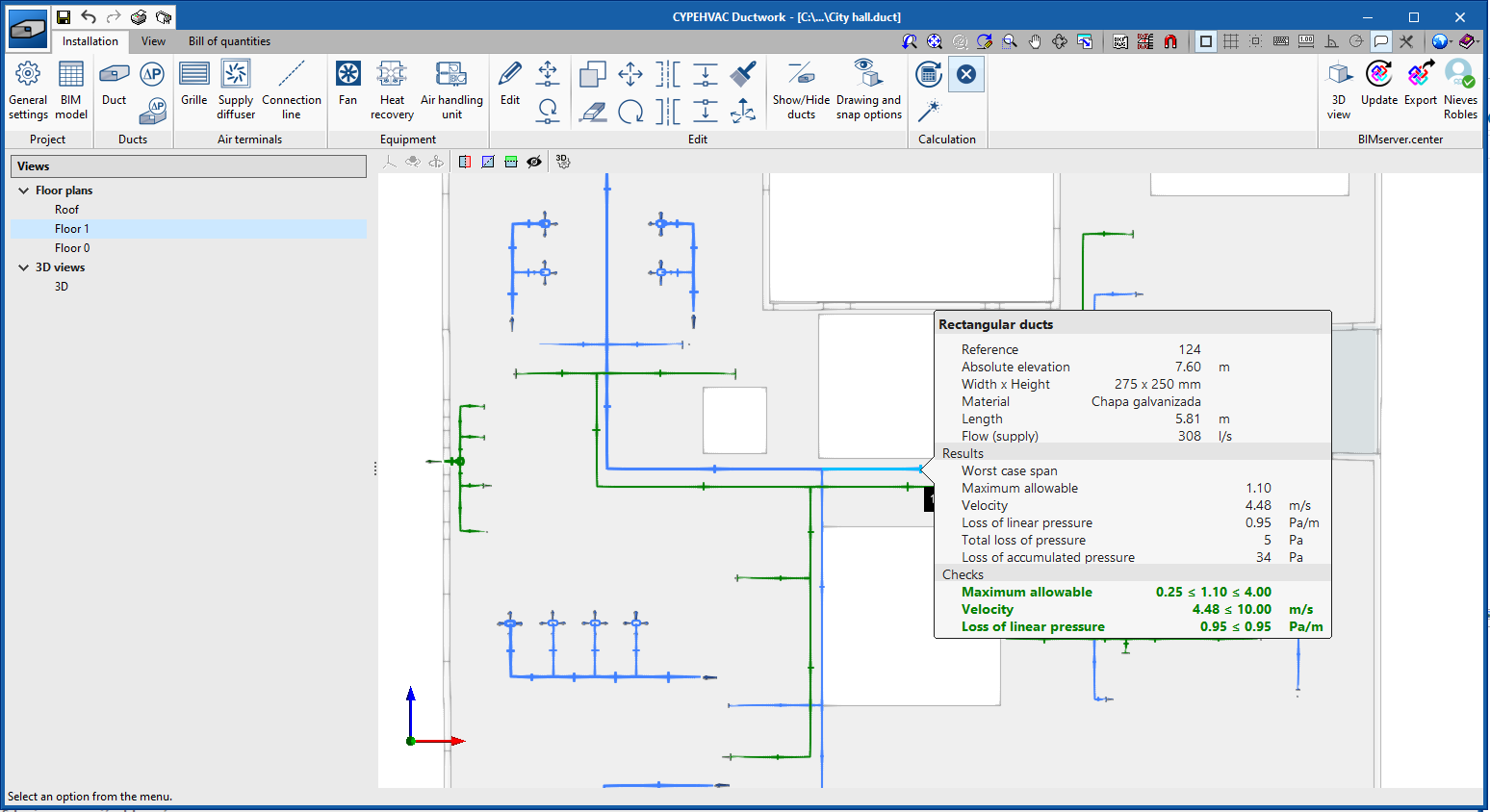
After carrying out the calculation, "CYPEHVAC Ductwork" shows on screen, when positioning the cursor over an installation element, the calculated air flow and pressure loss as well as the installation compliance with the ranges defined in the calculation options. The program highlights on screen the duct sections belonging to the path that presents the greatest accumulated pressure loss in the network.
In addition, "CYPEHVAC Ductwork" allows the following documentation to be obtained:
- Floor plans (DXF)
- Duct network calculation report (PDF)
- Quantities in FIEBDC-3 format (BC3)
- Materials list (PDF)
Open BIM workflow
This application is integrated into the Open BIM workflow via the BIMserver.center platform. The program currently exchanges the following information with the linked BIM project:
- Imports
- Ventilation flows
"CYPEHVAC Ductwork" imports ventilation flows calculated with “CYPETHERM LOADS” and “Open BIM COVID-19”.
- Thermal loads of the spaces
"CYPEHVAC Ductwork" imports thermal loads of the spaces calculated with "CYPETHERM LOADS".
- 3D view
"CYPEHVAC Ductwork" shows the 3D view of all the models that are imported during the connection with the BIM model.
- Ventilation flows
- Exports
"CYPEHVAC Ductwork" exports a file in IFC format that contains:
- The 3D model of the installation (GLTF)
"CYPEHVAC Ductwork" provides the linked BIM model with the 3D representation of the duct installation in GLTF format so that it is visible in all 3D views of the applications connected to the project’s BIM model.
- The following documentation
- Floor plans (PDF)
- Duct network calculation report (PDF)
- Materials list (PDF)
- The 3D model of the installation (GLTF)
More information
Download, resources and available languages, license requirements...
Tel. USA (+1) 202 569 8902 // UK (+44) 20 3608 1448 // Spain (+34) 965 922 550 - Fax (+34) 965 124 950